4. Configuration
This chapter describes the pyCoilGen confiuration parameters.
Note: All values are specified in SI units, i.e. metre, Ampere, Tesla.
4.1. Basic Settings
output_directory(Type:str, Default:Current working directory)The output directory where intermediate images and the final output will be written to.
project_name(Type:str, Default:'CoilGen')A project name. The project name is used to create output files.
persistence_dir(Type:str, Default:'debug')The directory where project snapshots are written. A snapshot of the internal state is automatically written to this location when any unhandled exception occurs.
debug(Type:int, Default:0)The debug verbosity level: 0 = None, 1 = Basic, 2 = Verbose.
The debug verbosity level only has any effect if logging is configured to include the debugging level. See
parameter_where_log_level_is_set.if __name__ == "__main__": # Set up logging log = logging.getLogger(__name__) logging.basicConfig(level=logging.DEBUG) ...
geometry_source_path(Type:str, Default:Current Working Directory + '/Geometry_Data')The directory where
.stlgeometry files are located.
4.2. Mesh Creation
There are three mesh geometries: coil, target and shield.
The coil mesh defines the surface upon which the coil winding path must be computed. This geometry is required.
The target field is a vector field of co-ordinates and magnitudes. This geometry is required. It may either be specified by loading an existing target field, which provides both the co-ordinates and the magnitudes at each co-ordinate, or by separately specifying the co-ordinates and a gradient field equation.
The shield mesh is an optional geometry which defines an additional surface where the magnetic field must be suppressed.
These mesh geometries can either be loaded from a pre-optimised file or specified individually using mesh creation builders.
4.2.1. Mesh Geometry
All figures in this document are rendered with the X-, Y-, and Z-axes as shown below:
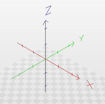
A 3D rendered view of the axis geometry.
4.2.2. Coil Meshes
The purpose of pyCoilGen is to generate a coil wire path on a coil mesh surface or surfaces to produce a desired target field.
The coil mesh surface can be specified using a coil mesh builder and a corresponding builder configuration parameter.
coil_mesh(Type:str, Default:'none')Define the coil surface for the wire path.
Specify the mesh builder to create the coil mesh surface(s). The corresponding creation builder parameter must also be provided.
coil_mesh_file(Type:str, Default:'none') (deprecated)Either specify the filename of an
.stlfile to be loaded fromgeometry_source_path, or use one of the mesh creation builders with the builder’s corresponding parameters.
4.2.2.1. Subdividing the Mesh
Once the mesh has been loaded, the mesh resolution can be increased using subdivision.
iteration_num_mesh_refinement(Type:int, Default:0)The number of refinement iterations of the mesh. At each iteration, every mesh face is subdivided into four faces.
4.2.2.2. Parameterise Mesh
The 3D coil winding surface needs to be projected onto a 2D plane in order to perform further processing.
surface_is_cylinder_flag(Type:bool, Default:True)Provide a hint to
pyCoilGenthat the 3D coil can be projected onto 2D using a simple cylindrical projection.
If the cylindrical projection is inappropriate then an iterative mesh parameterisation approach is used.
circular_diameter_factor(Type:float, Default:1)Circular diameter factor for projecting the 3D coil mesh to 2D.
4.2.3. Target Field
The purpose of pyCoilGen is to generate coils that produce a desired target field. This target field could be a
gradient field or a generic target field.
The target vector field can either be specified using a mesh or a sphere to define the co-ordinates and the
field_shape_function to define the magnitudes, or loaded from a NumPy pickle file. The NumPy pickle file takes
precedence, if specified.
A gradient field is specified by using a field shape function.
4.2.3.1. Specifying the Target Field Co-ordinates Using a Mesh
The mesh defines the boundary of the target field and these parameters fine-tune the target field point selection.
target_mesh(Type:str, Default:'none')Specify the mesh creation instruction to create the target field co-ordinates. The corresponding builder creation parameter must also be provided.
target_mesh_file(Type:str, Default:'none') (deprecated)Specify the STL mesh file to define the target field.
use_only_target_mesh_verts(Type:bool, Default:False)If True, indicates that only the vertices of the mesh are to be used. By default the target volume is populated with points.
target_region_resolution(Type:int, Default:10)Defines how many target points to create per dimension within the target region.
Only used if
use_only_target_mesh_vertsisFalse.
4.2.3.2. Specifying the Target Field Co-ordinates Using a Sphere
When target mesh is not specified, then the target field co-ordinates are created using a spherical volume, centred at the co-ordinates origin.
target_region_radius(Type:float, Default:0.15)The radius of the spherical target field.
The target field co-ordinates are then created by sub-dividing the radius using
target_region_resolution, which defines how many co-ordinates to create along each axis.set_roi_into_mesh_center(Type:bool, Default:False)This flag is used to set the ROI into the geometric center of the coil mesh(es). If set, the centre of the target sphere is moved to the mean of the coil mesh vertices.
4.2.3.3. Specifying the Gradient Field Shape Function
Once the target field co-ordinates have been specified, then gradient field vectors can be calculated.
field_shape_function(Type:str, Default:'x')The spatial function that defines the analytical function of the
zcomponent of the vector field. For example,xmeans a linear gradient in thex-direction of thezcomponent.target_gradient_strength(Type:float, Default:1)The gradient field strength in mT/m/A.
4.2.3.4. Using a NumPy Pickle file
A NumPy Pickle file can be used to provide a custom vector field consisting of both co-ordinates and field magnitude.
target_field_definition_file(Type:str, Default:'none')The name of the NumPy pickle file that contains the target field co-ordinates and field value.
The target field definition file allows users to specify non-analytical fields.
If used, the target field file is loaded from the
target_fieldsdirectory.target_field_definition_field_name(Type:str, Default:'none')The field name of the target field definition within the NumPy pickle file.
Target Field File Structure
The target field NumPy pickle file consists of a single array containing a dictionary with at least two key-value
pairs: coords and another key-value pair.
The coords key-value pair must be a 3 by M array which specifies the of x,y and z-coordinates of each target field
point.
The other key-value pair, which provides the magnetic field component, is specified with the target_field_definition_field_name
property. The value may either by a single array of the same length (M) as coords, or a 3 by M array.
If the value is a 1-D array, then it is interpreted to be the z-component of the target field and will be used to construct the required 3-D array by setting the x- and y-components to zero.
The following code snippet shows how to create the file from existing data.
def save_bfield_file(filename: str, coords: np.ndarray, vector_field: np.ndarray):
    data = {
      'coords': coords,       # Assuming that coords is a (3,m) array of float.
      'b_field': vector_field # Assuming that vector_field is either an (m,) or (3,m) array of float.
      }
    np.save(f'target_fields/{filename}.npy', [data], allow_pickle=True)
The data would be loaded by using:
  parameters = {
      ...
      'target_field_definition_file': f'{filename}.npy',  # Target field file name
      'target_field_definition_field_name': 'b_field',    # Target field key name
      ...
  }
  solution = pyCoilGen(log, parameters)
4.2.4. Shield Mesh
The optional shield mesh specifies where the magnetic field must be zero, for example for suppressed outer regions in active shields.
shield_mesh(Type:str, Default:'none')Specify the mesh creation instruction to create the shield mesh co-ordinates. The corresponding builder parameter must also be provided.
secondary_target_mesh_file(Type:str, Default:'none') (deprecated)File of the secondary target mesh.
secondary_target_weight(Type:float, Default:1)Weight for the secondary target points.
4.2.5. Mesh Creation Builders
Any mesh geometry can be specified using the installed mesh builders.
The full list of available mesh builders can be retrieved from the command-line using the help option to the mesh constructor parameter, for example:
pyCoilGen --coil_mesh help
To use one of the builders, set the appropriate mesh geometry parameter (coil_mesh, target_mesh, shield_mesh) to one of the available builders and define the builder parameters. For example, to set the coil mesh to a cylinder and a planar target region:
arg_dict = {
    ...
    'coil_mesh': 'create cylinder mesh',
    'cylinder_mesh_parameter_list': [0.8, 0.154, 30, 30, 0, 0, 1, 0],
    ...
    'target_mesh': 'create planar mesh',
    'planar_mesh_parameter_list': [0.2, 0.2, 20, 20, 1, 0, 0, 0, 0, 0, 0],
    ...
}

solution = pyCoilGen(log, arg_dict)
NOTE: You cannot use the same builder for the different mesh geometries as only one builder parameter can be passed to pyCoilGen.
The mesh builders are:
create cylinder meshCreate a cylindrical mesh defined by
cylinder_mesh_parameter_list(Type:list of numeric, Default:[0.8, 0.3, 20, 20, 1, 0, 0, 0])cylinder_height (`float`): Height of the cylinder. cylinder_radius (`float`): Radius of the cylinder. num_circular_divisions (`int`): Number of circular divisions. num_longitudinal_divisions (`int`): Number of longitudinal divisions. rotation_vector_x (`float`): X-component of the rotation vector. rotation_vector_y (`float`): Y-component of the rotation vector. rotation_vector_z (`float`): Z-component of the rotation vector. rotation_angle (`float`): Rotation angle.
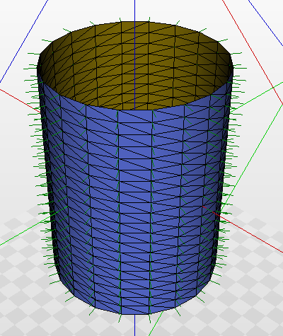
A 3D rendered view of the default cylindrical mesh.
create planar meshCreate a planar mesh defined by
planar_mesh_parameter_list(Type:list of numeric, Default:[0.25, 0.25, 20, 20, 1, 0, 0, 0, 0, 0, 0])planar_height (`float`): Height of the planar mesh. planar_width (`float`): Width of the planar mesh. num_lateral_divisions (`int`): Number of divisions in the lateral direction. num_longitudinal_divisions (`int`): Number of divisions in the longitudinal direction. rotation_vector_x (`float`): X component of the rotation vector. rotation_vector_y (`float`): Y component of the rotation vector. rotation_vector_z (`float`): Z component of the rotation vector. rotation_angle (`float`): Rotation angle in radians. center_position_x (`float`): X component of the center position. center_position_y (`float`): Y component of the center position. center_position_z (`float`): Z component of the center position.
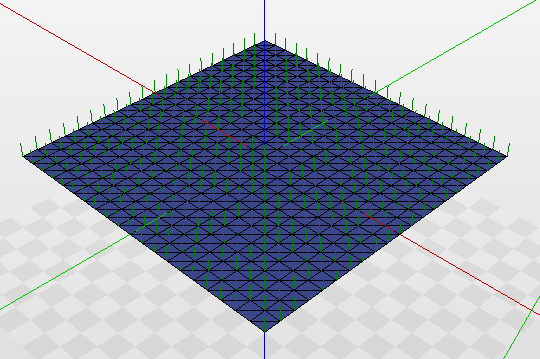
A 3D rendered view of the default planar mesh.
create bi-planar meshCreate a bi-planar mesh defined by
biplanar_mesh_parameter_list(Type:list of numeric, Default:[0.25, 0.25, 20, 20, 1, 0, 0, 0, 0, 0, 0.2])planar_height (`float`): Height of the planar mesh. planar_width (`float`): Width of the planar mesh. num_lateral_divisions (`int`): Number of divisions in the lateral direction. num_longitudinal_divisions (`int`): Number of divisions in the longitudinal direction. target_normal_x (`float`): X-component of the target normal vector. target_normal_y (`float`): Y-component of the target normal vector. target_normal_z (`float`): Z-component of the target normal vector. center_position_x (`float`): X-coordinate of the center position. center_position_y (`float`): Y-coordinate of the center position. center_position_z (`float`): Z-coordinate of the center position. plane_distance (`float`): Distance between the two planes.

A 3D rendered view of the default bi-planar mesh.
create circular meshCreate a circular mesh defined by
circular_mesh_parameter_list(Type:list of numeric, Default:[0.25, 20, 1.0, 0.0, 0.0, 0.0, 0.0, 0.0, 0.0])radius (`float`): Radius of the mesh. num_radial_divisions (`int`): Number of divisions in the radial direction. rotation_vector_x (`float`): X component of the rotation vector. rotation_vector_y (`float`): Y component of the rotation vector. rotation_vector_z (`float`): Z component of the rotation vector. rotation_angle (`float`): Rotation angle in radians. center_position_x (`float`): X component of the center position. center_position_y (`float`): Y component of the center position. center_position_z (`float`): Z component of the center position.

A 3D rendered view of the default circular mesh.
create stl meshCreate the mesh from the file specified with
stl_mesh_filename(Type:str, Default:none)The following file types (file extensions) are supported:
STL: Stereolithography NB: pyCoilGen assumes that STL values are in metres.
PLY: Polygon
OBJ: Wavefront .obj
The mesh is loaded from the
geometry_source_pathunless thestl_mesh_filenamecontains a path separator (\or/), in which case the file is loaded from that path. Relative paths are loaded with respect to the current directory.NB: Ensure that all mesh dimensions are in metre units.
4.3. Discretisation and Calculation of Field Variables
4.3.1. Winding Coil Contribution and Target Field Sensitivity
The magnetic field contribution and the target field sensitivity is calculated at every corresponding co-ordinate.
gauss_order(Type:int, Default:2)This parameter determines the number of Gauss integration points used in the winding magnetic field calculations.
4.3.2. Winding Coil Resistance
The winding coil resistance affects the gradient magnetic field due to the winding coil.
specific_conductivity_conductor(Type:float, Default:0.018e-6)The conductivity of the winding coil.
conductor_thickness(Type:float, Default:0.005)The thickness of the sheet current density within the stream function representation.
4.3.3. Stream Function
The stream function represents the relationship between the coil parts and the target field.
pyCoilGen performs an optimisation calculation of the stream function.
sf_opt_method(Type:str, Default:'tikhonov')The stream function optimization method.
tikhonov_reg_factor(Type:float, Default:1)Tikhonov regularization factor for the stream function optimization, for weighting the coil’s resistance, and hence the dissipated power.
minimize_method(Type:str, Default:'SLSQP')The minimisation method to use in the the NumPy
minimizefunction. Ifsf_opt_methodis not'tikhonov', then the NumPyminimizefunction is used.minimize_method_parameters(Type:str, Default:"{'tol': 1e-6}")Additional minimize method parameters.
minimize_method_options(Type:str, Default:"{'disp': True, 'maxiter' : 100}")Additional minimize method options, specific to the method.
Please refer to the scipy.optimize.minimize API documentation
for more information on optimization-related parameters.
4.4. Pre-calculated Mesh and Stream Function
The stream function optimisation is a time-consuming process and dependent only on the input coil surfaces, target volume and optimisation parameters, above.
Users wishing to explore coil designs can save the optimised data once, then re-load it while changing the remaining parameters, below.
4.4.1. Save
The combined mesh and stream function can be persisted for subsequent re-use.
sf_dest_file(Type:str, Default:'none')The filename (without extension) where to write the optimised stream function and other data to storage.
The file will be written to the
Pre_Optimized_Solutionsdirectory unless the filename contains any path delimiters (/or\). If the filename contains path delimiters, then the path is used as-provided. It is the user’s responsibility to ensure that the path already exists.
NOTE: If they are both specified, sf_source_file takes precedence over sf_dest_file.
4.4.2. Load
A pre-existing mesh and optimised stream function solution can be loaded from persistence.
sf_source_file(Type:str, Default:'none')The filename (without extension) of the file of the already optimized stream function.
The file is loaded from the
Pre_Optimized_Solutionsdirectory unless the filename contains any path delimiters (/or\). ThepyCoilGen_Datadirectory is automatically included, if installed. If the filename contains path delimiters, then the path is used as-provided.
4.5. Build Contour Lines
The optimised current density must be analysed to determine the candidate wire paths. This is done by computing the equipotential contours.
4.5.1. Contour Parameters
levels(Type:int, Default:10)The number of potential levels. This determines the number of coil windings.
level_set_method(Type:str, Default:'primary')The method for calculating the level sets. Can be one of ‘primary’, ‘combined’ or ‘independent’.
The contour levels are calculated from the stream function with contributions from the different coil meshes (if more than one), according to the level set method.
Use ‘primary’ to calculate the contour potentials from primary coil mesh only.
Use ‘combined’ to calculate the potentials from the combined mesh.
Use ‘independent’ to calculate the potentials for each coil mesh independently.
The best method depends on
pyCoilGen. Users can examine the final computed target field and computed errors to inform their decision.pot_offset_factor(Type:float, Default:1/2)The factor to control the contour level step, based on the stream function range.
smooth_factor(Type:int, Default:1)The number of points along the contour to be used for smoothing.
Each point is replaced with the moving average of the specified number of neighbouring points. Smoothing only takes place when the
smooth_factoris greater than 1.min_loop_significance(Type:int, Default:1)The minimal required field contribution (as a percent) to the target field. Contours that contribute less than this are deleted.
skip_calculation_min_winding_distance(Type:bool, Default:True)A flag to skip calculation of minimum distance between calculated contour lines.
pyCoilGencan calculate the PCB track width using the minimum width between contours if this flag isFalse.
4.6. Contour Topology
Once the equipotential contours have been identified, they are processed and grouped topologically.
Figure showing stream function discretization and contour generation
4.6.1. Topology Parameters
Figure showing details of contour interconnections
Neighbouring equipotential contours within a topological group are cut and joined with their neighbours. In order to reduce distortions induced by the cuts, they are performed along the intersection of the plane oriented with the magnetic field and the coil surface. Each contour thus has two cut points, one in the positive B0 direction and one against the B0 direction. These cut locations are termed “high” and “low” cuts, respectively.
4.6.2. Interconnect Contours / Build Wire Path
Connect the groups and shift the return paths over the surface.
force_cut_selection(Type:list, Default:[])The direction of cuts that join neighbouring contours, to form a topological group. The allowed options are
'high'or'low'.The array must either contain a single entry, which is used for all cut points, or match the number of topological groups, which is displayed by
pyCoilGenduring processing.cut_plane_definition(Type:str, Default:'nearest')The orientation of the cut plane used to join neighbouring contours is in the direction of the closest contour point to the group centre, by default. Can be one of
nearestorB0.This parameter allows to specify that the orientation should be in the
B0direction instead.b_0_direction(Type:float array, Default:[0, 0, 1])Direction (vector) along which the interconnections will be aligned.
interconnection_cut_width(Type:float, Default:0.01)Width (in metres) of the cut used to connect neighbouring contours and to join contour groups to form a single wire path.
4.6.3. Return Paths
These parameters affect the generation of the return paths (Figure 4(c)).
skip_normal_shift(Type:bool, Default:False)If True, skips the shifting of return paths around the contour loop.
Shifting the return paths helps to align segments so that multiple segments of a single return path can all be raised together.
normal_shift_length(Type:float, Default:0.001)Distance in metres which intersecting wire paths will be separated along the normal direction of the surface.
normal_shift_smooth_factors(Type:list of 3 integers, Default:[2, 3, 2])Parameters used to smooth the shape of the return paths that are displaced in the direction of the coil mesh normal.
4.7. Generate Outputs
The primary purpose of pyCoilGen is to calculate the wire path of the coil that produces the desired target field.
4.7.1. Generate Cylindrical PCB Output
pyCoilGen can optionally generate a PCB wire path that is suitable for wrapping around a cylinder.
make_cylindrical_pcb(Type:bool, Default:False)If True, generates a rectangular PCB pattern to wrap around a cylinder.
pcb_interconnection_method(Type:str, Default:'spiral_in_out')Interconnection method for PCB: ‘spiral_in_out’ or ‘other’.
pcb_spiral_end_shift_factor(Type:int, Default:10)Factor (as a percent) to shift the open ends of the spirals in order to avoid overlaps.
4.7.2. Generate 3D Wire Path
pyCoilGen can optionally generate a 3D representation of the coil by sweeping out a conductor profile along the computed wire path.
skip_sweep(Type:bool, Default:False)If True, skips the generation of a volumetric (3D) coil body.
The calculated 3D surface is stored in the
layout_surface_meshproperty.cross_sectional_points(Type:list of float, Default:[0, 0])This parameter describes the 2D profile of the conductor surface.
The default of
[0,0]instructspyCoilGento generate a 10-sided circular profile with a radius specified by theconductor_thicknessparameter.A custom shape defined by specifying the x/y co-ordinates in metres in a 2xm array of the form
[[x0, x1, x2, x3, ...], [y0, y1, y2, y3, ...]].NB: The co-ordinates of the 2xm array should trace a ‘clockwise’ path about the origin to ensure that the normals are outward in the resulting 3D surface:
  arg_dict = {
    ...
        'cross_sectional_points': np.array([np.sin(np.linspace(0, 2 * np.pi, 10)),
                                          np.cos(np.linspace(0, 2 * np.pi, 10))]) * 0.01,
    ...
  }
4.8. Evaluate Results
Once pyCoilGen has calculated the wire path, it can also calculate some related values.
4.8.1. Calculate Inductance
pyCoilGen uses FastHenry2 to calculate the inductance and resistance of the wire path.
skip_inductance_calculation(Type:bool, Default:False)If True, skips calculating the resistance and inductance of the coil solution.
conductor_cross_section_width(Type:float, Default:0.002)Cross-section width of the conductor (for the inductance calculation) in metres.
conductor_cross_section_height(Type:float, Default:0.002)Cross-section height of the conductor (for the inductance calculation) in metres.
fasthenry_bin(Type:str, Default:OS dependent)Specify the location of the
FastHenry2binary.The default directory is determined by the host operating system.
On Microsoft Windows, the default installation location is
'C:\Program Files (x86)\FastFieldSolvers\FastHenry2\FastHenry2.exe', otherwise, it is set to'/usr/bin/fasthenry'.
4.8.2. Evaluate Target Field Errors
skip_postprocessing(Type:bool, Default:False)If True, skips calculating the field errors during post-processing.
4.9. Export Data
Data from the computed coil solution can be exported, for example to export the swept conductor path to a CAD file.
save_stl_flag(Type:bool, Default:True)If True, uses the provided CAD exporter to export data once the processing has completed.
4.9.1. Data Exporters
The full list of available exporters can be retrieved from the command-line using the help option to the exporter, for example:
pyCoilGen --exporter help
To use one of the exporters, set the exporter parameter to one of the available exporters and define the exporter parameters.
The CAD exporter is enabled by default to export the coil surface and conductor mesh to a PLY file, using the following parameters:
arg_dict = {
    ...
    'exporter': 'export CAD file',
    'CAD_filename': '{project}_{mesh}_{part_index}_{field_function}.ply',
    ...
}

solution = pyCoilGen(log, arg_dict)
The supported exporters are:
export CAD fileExport the surface and coil conductor meshes to the file specified by
CAD_filename(Type:str, Default:'{project}_{mesh}_{part_index}_{field_function}.stl')The following substitutions are available and will be replaced with the corresponding content:
{output_dir}: Replaced withoutput_directory.{project}: Replaced withproject_name.{field_function}: Replaced withfield_shape_function, stripped of any*,^,\and/symbols.{part_index}: Replaced with the current, zero-based, coil index.{mesh}: Replaced withwireorsurfacefor each of the wire path or coil surfaces.
If
{mesh}is not present, only the swept wire path will be exported.The following file types are supported:
STL: Stereolithography
PLY: Polygon
OBJ: Wavefront .obj